INTRODUCTION
Grinding is the process of removing metal by the application of abrasives which are bonded to form a rotating wheel. When the moving abrasive particles contact the workpiece, they act as tiny cutting tools, each particle cutting a tiny chip from the workpiece. It is a common error to believe that grinding abrasive wheels remove material by a rubbing action; actually, the process is as much a cutting action as drilling, milling, and lathe turning. The grinding machine supports and rotates the grinding abrasive wheel and often supports and positions the workpiece in proper relation to the wheel. The grinding machine is used for roughing and finishing flat, cylindrical, and conical surfaces; finishing internal cylinders or bores; forming and sharpening cutting tools; snagging or
removing rough projections from castings and stampings; and cleaning, polishing, and buffing surfaces. Once strictly finishing machines, modem production grinding machines are used for complete roughing and finishing of certain classes of work. Grinding machines have some special safety precautions that must be observed.
SAFETY PRECAUTIONS
Grinding machines are used daily in a machine shop. To avoid injuries follow the safety precautions listed below.
a)Wear goggles for all grinding machine operations.
b)Check grinding wheels for cracks before mounting.
c)Never operate grinding wheels at speeds in excess of the recommended speed.
d)Never adjust the workpiece or work mounting devices when the machine is
operating
e)Do not exceed recommended depth of cut for the grinding wheel or machine.
f)Remove workpiece from grinding wheel before turning machine off.
g)Use proper wheel guards on all grinding machines.
TYPES OF GRINDING MACHINES
There are many forms of grinding, but the four major industrial grinding processes are:
*Cylindrical grinding
*Internal grinding
*Centerless grinding
*Surface grinding
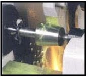
In cylindrical grinding, the workpiece rotates about a fixed axis and the surfaces machined are concentric to that axis of rotation. Cylindrical grinding produces an external surface that may be straight, tapered, or contoured. The basic components of a cylindrical grinder include a wheelhead, which incorporate the spindle and drive motor; a cross-slide that moves the wheelhead to and from the workpiece; a headstock, which locates, holds, and drives the workpiece; and a tailstock, which
holds the other end of the work. Internal diameter or "I.D." grinders finish the inside of a previously drilled, reamed, or bored hole, using small grinding wheels at high rpm.
The principle elements of an internal grinding machine are the workhead, which holds the work and has its own drive; and the wheelhead, which is the internal grinding spindle. In addition to the rotary motions of work and wheel, an internal grinder has a traverse movement to bring the wheel to and from the work zone, and a reciprocating spindle movement for both the wheel's approach to the work surface and for the feed movement of the wheel during grinding. Several different internal contours can be produced within a workpiece using I.D. grinding. In centerless grinding, the workpiece rotates between a grinding wheel and a regulating drive
wheel. The work is supported from below by a fixed work-rest blade. The two basic modes of centerless grinding are "thru-feed" and "in-feed" or "plunge" mode. In the thru-feed mode, the work proceeds in the axial direction through the slowly narrowing gap between the grinding wheel and the regulating wheel. Work is advanced by the axial force exerted on it by the rotating surface of the regulating wheel. This is a highly productive form of grinding in that a number of workpieces can be ground simultaneously and in a continuous stream. The "infeed" mode is used for work with projecting heads that would prohibit "thru-feeding," the work is placed on the work-rest blade while one wheel is retracted and fed to an end stop. The wheel is then brought back, reducing the gap between the wheels, grinding the work. Surface grinding produces flat, angular, or contoured surfaces by feeding work in a horizontal plane beneath a rotating grinding wheel. Work is most often magnetically attached to the table, and may be ground by either a traversing or rotating movement of the table. Most surface grinding machines use a horizontal spindle which adjusts up and down allowing either theedge or the face of the wheel to contact the work.
GENERAL GRINDING OPERATIONS
Efficient grinding depends primarily upon the proper setup of the machine being used. If the machine is not securely mounted, vibration will result, causing the grinder to produce an irregular surface. Improper alignment affects grinding accuracy, and it is good practice to check the security and plumb of the machine every few months. It is advisable to place a strip of cushioning material under the mounting flanges, along with any necessary aligning shims, to help absorb vibration. When a grinding wheel is functioning properly, the abrasive grains cut very small chips from the workpiece and at the same time a portion of the bond of the wheel is worn away. As long as the bond is being worn away as fast as the abrasive grains of the wheel become dull, the wheel will continue to work well. If the bond is worn away too rapidly, the wheel is too soft and will not lasts long as it should. If the cutting grains wear down faster than the bond, the face of the wheel becomes glazed and the wheel will not cut freely.
GRINDING SPEEDS AND FEEDS
In grinding, the speed of the grinding wheel in fpm and the feed of the grinding wheel are as important as, and sometimes more important than, proper wheel selection. Occasionally, the grinder spindle should be checked with a tachometer to make sure it is running at its specified rpm (revolutions per minute). Too slow a speed will result in waste of abrasive, whereas an excessive speed will cause a hard grinding action and glaze the wheel, making the grinding inefficient. The
feed of the grinding wheel will determine to a certain extent the finish produced on the work and will vary for different types and shapes of grinding wheels.
Factors Governing Speed

The various factors governing the speed in fpm of a grinding wheel are as described below;
Safety
The grinding wheel should never be run at speeds in excess of manufacturer's recommendations.
Usually, each grinding wheel has a tag attached to it which states the maximum safe operating
speed.
Condition of the Machine
Modern grinding machines and machines that are in good condition can safely turn a grinding wheel at speeds greater than machines that are older or in poor condition. Most grinding machines are equipped with spindle bearings designed for certain speeds which should not be exceeded. Poor quality will result from vibrations caused by inadequate rigidity or worn bearings that are not in the
best condition. High speeds will intensify these defects.
Material Being Ground
The material being ground will generally determine the grain, grade, structure, and bond of wheel to be selected. For example, if the wheel is too soft for the material being cut, an increase in speed will make the wheel act harder. Conversely, if the wheel is too hard, as lower speed will make the wheel act softer.
Type of Grinding Wheel
The type of grinding wheel employed for a particular operation is one of the major considerations in the proper selection of cutting speed. In general practice, the wheel will be selected for the material to be cut. The recommended cutting speed can then be determined by the wheel type, bond, and grade of hardness.
Calculating Wheel Size or Speeds
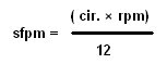
Grinding wheel speeds commonly used in precision grinding vary from 5,500 to 9,500 sfpm. The
wheel speed can change by changing the spindle speed or by using a larger or smaller wheel. To
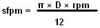
find the wheel speed in sfpm, multiply the spindle speed (rpm) by the wheel circumference (inches)
and divide the product by 12.
The maximum speed listed on a grinding wheel is not necessarily the speed at which it will cut best.The manufacturer decides the maximum speed based on the strength of the wheel. That speed provides a margin of safety and the wheel usually will cut better at a lower speed. One method used to determine the proper wheel speed is to set the speed between the minimum and maximum recommended by the manufacturer. Take a trial cut. If the wheel acts too soft, increase the speed. If it acts too hard, decrease the speed.
sfpm = Cutting speed of wheel (In surface feet per minute).
rpm = Revolutions per minute of wheel.
D = The calculated wheel diameter (in inches).
NOTE:
As a grinding wheel wears down and as it is continually trued and dressed, the wheel diameter decreases, resulting in loss of cutting speed. As this occurs, it is necessary to increase the rotational speed of the wheel or replace the wheel to maintain efficiency in grinding.
Work Speed for Cylindrical Grinding (Traverse)
In cylindrical grinding, it is difficult to recommend any work speeds since these are dependent upon whether the material is rigid enough to hold its shape, whether the diameter of the workpiece is large or small, and so forth. Listed below are areas to consider when performing cylindrical grinding:
*The larger the diameter of the workpiece, the greater is its arc of contact with
the wheel. The cutting speed suitable for one diameter of workpiece might be
unsuitable for another.
*The highest work speed that the machine and wheel will stand should be used for
roughing.
*The following cylindrical work speeds are only typical: steel shafts, 50 to 55
sfpm; hard steel rolls, 80 to 85 sfpm; chilled iron rolls, 80 to 200 sfpm; cast
iron pistons, 150 to 400sfpm; crankshaft bearings, 45 to 50 sfpm; and crankshaft
pins, 35 to 40 sfpm.
*Higher work speeds increase the cutting action of the wheel and may indicate
that a harder wheel and a smaller depth of cut be used to reduce wheel wear.
Work Speed for Surface Grinding
Surface grinding machines usually have fixed work speeds of approximately 50 sfpm or have variable work speed ranges between 0 and 80 sfpm. As with cylindrical grinding, the higher work speeds mean that more material is being cut per surface foot of wheel rotation and therefore more wear is liable to occur on the wheel.
Feeds
The feed of the grinding wheel is the distance the wheel moves laterally across the workpiece for each revolution of the piece in cylindrical grinding or in each pass of the piece in surface grinding.The following methods are recommended for determine feeds:
*The feed should be proportional to the width of wheel face and the finish
desired. In general,the narrower the face of the wheel, the slower must be the
traverse speed; the wider the wheel faces the faster can be the traverse speed.
*For roughing, the table should traverse about three quarter the wheel width per
revolution or pass of the workpiece.
*For an average finish, the wheel should traverse one-third to one-half the width
of the wheel per revolution or pass of the workpiece.
*In surface grinding with wheels less than 1 inch in width, the table traverse
speed should be reduced about one-half.
Depth of Cut
The depth of cut depends on such factors as the material from which the work is made, heat treatment, wheel and work speed, and condition of the machine. Methods for determining depth of cuts are recommended for determining feeds.
*In roughing, the cut should be as deep as the grinding wheel will stand, without
crowding or springing the work. The depth of cut also depends on the hardness of
the material. In cylindrical grinding, in addition to these factors, the cut
depends on the diameter of the work. In any case, experience is the best guide.
Generally, a cut of 0.001 to 0.003 inch in depth is used, depending on the size
and condition of the grinding machine.
*For finishing, the depth of cut is always slight, generally from 0.0005 inch to
as little as 0.00005 inch.
*An indication of the depth of cut is given by the volume of sparks thrown off.
Also, an uneven amount of sparks indicates that the workpiece or wheel is not
concentric.
COOLANTS
Most grinding machines are equipped with coolant systems. The coolant is directed over the point of contact between the grinding wheel and the work. This prevents distortion of the workpiece due to uneven temperatures caused by the cutting action. In addition, coolant keeps the chips washed away from the grinding wheel and point of contact, thus permitting free cutting. Clear water may be used as a coolant, but various compounds containing alkali are usually added to improve its
lubricating quality and prevent rusting of the machine and workpiece. An inexpensive coolant often used for all metals, except aluminum, consists of a solution of approximately 1/4 pound of sodium carbonate (sal soda) dissolved in 1 gallon of water. Another good coolant is made by dissolving soluble cutting oil in water. For grinding aluminum and its alloys, a clear water coolant will produce fairly good results.
CYLINDRICAL GRINDING
In cylindrical grinding, the workpiece rotates about a fixed axis and the surfaces machined are concentric to that axis of rotation. The basic components of a cylindrical grinder include a wheelhead, which incorporate the spindle and drive motor; a sliding table that moves the wheelhead to and from the workpiece; a headstock (Workhead), which locates, holds, and drives the workpiece; and a tailstock, which holds the other end of the work. Cylindrical grinding is divided
into three general operations: plain cylindrical, conical grinding (taper grinding), and internal grinding.
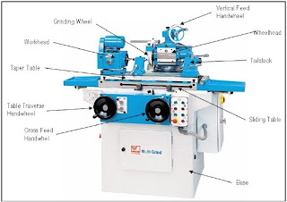
Universal Grinding Machine
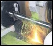
Cylindrical Grinding Operation
Plain Cylindrical Grinding
The step-by-step procedure for grinding a straight shaft is given below. The shaft has been roughly turned prior to grinding.
*Be sure the centers in the workhead and tailstock and the center holes in the
workpiece are in good condition.
*Position the workhead and tailstock and set the traverse stop dogs so that when
the workpiece is in place, the table will traverse (longitudinally) the proper
distance to grind the surface.
*Adjust the workhead speed mechanism to get the proper rotational speed.
Normally, you should use a slow speed for roughing and a high speed for
finishing.Set the longitudinal traverse speed so the work advances from two
thirds to three-fourths the thickness of the wheel during each revolution of the
workpiece.
*Set the workpiece in place and clamp the tailstock spindle after making sur
that both
*centers are seated properly and that the driving dog is not binding.
Select and mount the grinding wheel.
*Start the spindle motor, hydraulic power pump, and coolant pump. After the
machine has
*run for a few minutes, start the coolant flow and dress the wheel.Using the
cross traverse mechanism, bring the wheel up to the workpiece and traverse the
table longitudinally by hand to see that the wheel will travel through the cycle
without
*hitting any projections. (About one-half of the wheel width should remain on the
work at each end of the longitudinal traverse stroke.) Clamp the table dogs in
the correct positions to limit longitudinal traverse. Start the workhead motor
and feed the grinding wheel in sufficiently to make a cleanup cut(a light cut
the entire length of the surface to be ground).
*Using power longitudinal traverse, take a cut. Then, disengage the power
traverse, stop the workhead motor and wheelhead rotation, and check the
workpiece for taper. Make any
*changes required. (If you are using the taper table attachment and you need to
make an adjustment at this point, dress the wheel again.)
Conical Grinding
Most conical grinding is performed in the same manner as plain cylindrical grinding. Once the grinding machine is set up, the table is swiveled until the correct taper per inch is obtained. Steep conical tapers are normally ground by swiveling the headstock to the angle of taper. Whichever method is used, the axis of the grinding wheel must be exactly at center height with the axis of the
work.
Internal Grinding
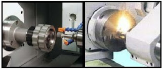
The internal grinding attachment is bolted to the wheel head on the universal tool and cutter grinder. The rpm is increased by placing a large pulley on the motor and a small pulley on the attachment.
The workpiece should be set to rotate in the direction opposite that of the grinding wheel. The following step-by-step procedure for grinding the bore of a bushing is outlined below as an
example.
*Set up the workpiece in an independent chuck and check and adjust its alignment.
*Mount the internal grinding attachment to the wheel head and adjust its position
so that the grinding wheel is centered vertically with the mounted workpiece.
*True and dress the grinding wheel.Set the proper wheel speed on the grinding
machine by adjusting the pulleys and belts connecting the wheel spindle to the
drive motor shaft.
*Set the proper rotational work feed. The speed should be 60 to 100 sfpm.
*Be sure sufficient clearance is allowed when setting the traversing speed so
that the grinding wheel will not strike any part of the workpiece or setup when
the wheel is fed into and retracted from the workpiece.
If two or more grinding wheels are used to complete internal grinding, true each wheel after mounting it to the spindle of the internal grinding attachment.
SURFACE GRINDING
Surface grinding or grinding flat surfaces, is characterized by a large contact area of the wheel with the workpiece, as opposed to cylindrical grinding where a relatively small area of contact is present. As a result, the force of each abrasive grain against the workpiece is smaller than that applied to each grain in cylindrical grinding. In surface grinding the grinding wheel should be generally softer in grade and wider in structure than for cylindrical grinding. Workpiece surfaces produced by grinding are influenced by the following factors:
* workpiece material - harder materials allow finer finishes
* type of wheel - fine grains yield finer finishes
* dressing procedure - improperly dressed wheels will mar the work surface
* feed rate - finer finishes are obtained with slower feed rates
* machine rigidity - older, worn machines yield a poor quality finish
* wheel condition - clogged wheels cannot produce a good finish
* lubricant cleanliness - coolant filtration removes waste that could damage
workpiece surface
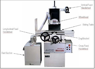
Surface Grinding Machine
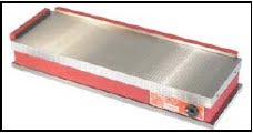
Work holding Devices
In most surface grinding operations, we will use one of two work holding devices, either a magnetic chuck or a universal vise. Since most surface grinding is done on flat workpieces, most surface grinders have magnetic chucks. These chucks are simple to use. The workpiece can mount directly on the chuck or on angle plates, parallels, or other devices mounted on the chuck. The magnetic chuck holds magnetic materials only. However steel clamps (a magnetic material) can be used to
laterally clamp non-magnetic materials for surface grinding. The universal vise can be used to grind complex angles on a workpiece. The vise can mount directly on the worktable of the grinder or on the magnetic chuck.
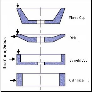
Grinding wheels
Grinding wheels come in various shapes. Each shape is selected to perform a specific job. The cylindrical wheel is the most common type. Its cutting surface is located at the periphery of the wheel. Wheels of this shape are often mounted on a plate. The straight cup wheel is designed to cut on the periphery and the side face at the same time. This type of wheel is often used to grind shoulders. The dish wheel is a tool and cutter grinding wheel. It is typically used to regrind end mills and has a specific shape to accomplish that. The flared cup wheel is also tool and cutter grinding wheel. There are several cup shapes available depending on the needs of the machinist. Grinding wheels can be custom dressed with a diamond tool to achieve nearly any shape desired.
Grinding Wheel
Surface Grinding Operation
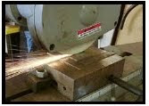
Surface Grinding
The following sequence is provided as a step-by-step example of a typical surface grinding operation.
* Adjust the surface grinding machine so that grinding head and worktable are
absolutely parallel.
* Place a grinding wheel of the proper grain, grade, structure, and bond on the
wheel spindle.
* Place the guard over the wheel and check security of all adjustable members of
the grinding machine for rigidity and lack of backlash.
* True and dress the grinding wheel.
* Place the workpiece on the magnetic chuck. Make sure the surface to be ground
is parallel to the worktable and the grinding wheel.
* Move the chuck lever to the position that energizes the magnetic field.
* Set the table stop dogs so the sliding table will move the work clear of the
wheel at each end of the stroke.
* Set the longitudinal traverse speed of the worktable.
* Set the cross traverse mechanism so the table moves under the wheel a distance
slightly less than the width of the wheel after each pass.
* Start the spindle motor, let the machine run for a few minutes, and then dress
the wheel.
* Feed the moving wheel down until it just touches the work surface; then use the
manual cross traverse handwheel to move the work clear of the wheel. Set the
graduated feed collar on zero to keep track of how much you feed the wheel into
the work.
* Feed the wheel down and engage the longitudinal power traverse. Use the cross
traverse handwheel to bring the grinding wheel into contact with the edge of
the workpiece.
* Engage the power cross traverse and let the wheel grind across the surface of
the workpiece. Carefully note the cutting action to decide if you need to
adjust the wheel speed or the work speed. Stop the longitudinal and cross
traverses and check the workpiece.


