A lathe is the forerunner of all machine. It is the most important machine used in
any workshop. Initially it was used for wood turning. After Henry Maudslay developed
the sliding carriage in 1800, a lot of development has taken place and lathes are now
available in numerous sizes and shapes.
A lathe removes the material by rotating the workpiece against a single point cutting tool.
The part to be machined can be held between two rigid support called centres, or by
someother device such as a chuck or face plate, that is screwed or secured to the end of
the spindle.
Turning means the part is rotating while it is being machined. The starting material is
usually a workpiece that has been made by other processes, such as casting, forging,
extrusion or drawing.
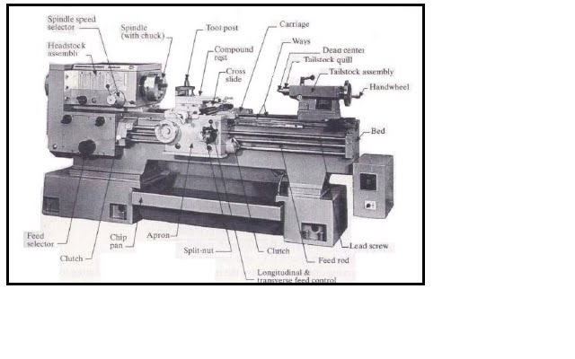
PART OF A LATHE
Bed. The bed of a lathe consists of two heavy parallel sides having ways. It is held rigidly
by cross girths supported by cast iron supports.
Headstock. It is situated at the left-hand and of the bed. It consists of a headstock casing
and supports the spindle and driving arrangement. The steel spindle is hollow, so that the
bars can be passed through it if necessary. The spindle nose of the spindle is threated to
hold the chuck or face plate by screwing it on
Tailstock. This is a counterpart of the headstock and is located opposite it on the ways of
the bed. It consists of a tapeset hole, adjusting screw and handwheel. It is used for
supporting and feeding drills, reamers and centres.
Carriage. The carriage is a moving part that slides over the ways between the headstock
and the tailstock. It consists of a saddle and apron, and also carries the compound rest.
Feed Rod and Lead Screw. The feed rod is powered by a set of gears from the headstock.
It rotates during the operation of the lathe and provides movement to the carriage and the
cross-slide by means of gears, a friction clutch and a keyway along the length of the rod.
Closing a split nut around the lead screw engages it with the carriage; it is also used for
cutting threads accurately.
TOOL LIFE
The time for which a tool keeps its machining capacity between two regrinding
operations is known as tool life. It can be estimated by the number of pieces machined
between tool regrinds. Since a considerable time is wasted in tool regrinding and resetting
on the machine, it pays to enhance tool life. To this end, the following factors need to be
considered.
* Cutting speed of the tool. Increased cutting speed decreases tool life.
* The shape of the tool and its angles.
* The ratio of feed and depth of cut.
* The rigidity of the tool, workpiece and machine.
* The nature and quantity of the cutting fluid.
* Tool setting in relation to the workpiece.
* Nature of the material being cut
* Chemical composition of the tool.
* Heat treatment operations carries out on the tool.
OPERATION PERFORMED BY A LATHE / TURNING
The following processes are capable of producing a wide variety of shapes:
* Turning, to produce straight, conical, curved, or grooved workpieces such
as shafts, spindle and pins.
* Facing, to produce a flat surface at the end of the part, which is useful for
that parts that are attached to other components, or face grooving to
produce grooves for O-ring seats.
* Boring, to enlarge a hole or cylindrical cavity by made by a previous
process or to produce circular internal grooves.
* Drilling, to produce a hole, which may be followed by boring to improve
its accuracy and surface finish.
* Parting, also called cutting off, to cut a piece from the end of a part , as is
done in the production of slug or blanks for additional processing into
discrete products.
* Threading, to produce external or internal threads.
* Knurling, to produce a regularly shaped roughess on cylindrical surfaces,
as in maling knobs

Various cutting operations that can be performed on a lathe. Note that all parts have circular symmetry.

Illustration of Boring, Knurling and Drilling operations.

RPM CALCULATION
- RPM = Revolution per minute (rotational speed of the workpiece)
- CS = Cutting Speed
- D = Diameter (workpiece)

EQUIPMENTS / APPARATUS
1. Workpiece diameter Ø 32 mm x 150 mm
2. Lathe machine with accessories such as tool post, drill chuck, etc.
3. Safety attire such as goggles, safety jacket, etc.
4. Cutting tool
5. Knurling tool
6. Grooving tool
7. Drill
8. Vernier caliper for measurement
PROCEDURES
1. Measure and mark your workpiece.
2. Open up the chuck jaws slightly larger than the diameter of the workpiece.
3. Insert the workpiece and center the workpiece at the chuck mount and the feed
end.
4. Tighten the workpiece securely
5. Install the tool into the tool rest
6. Determine the main spindle rpm
7. Set the main spindle speed select levers to the closest rpm.
8. Rotate the main spindle forward.
9. Approach the tool tip to the workpiece end, and cut into the end in the spindle
axis direction.
10.Use the scale on the tool rest feed handle to determine cutting depth.
11.Apply (5) to (9) for rough cutting on endface and outside diameter.
12.Consult with your engineers if you facing difficulties.
Note: Before start your project, make sure to follow all the safety procedure
Lathe Machine Project for Engineering Skills II ECT 200

NOTE :
1. ALL DIMENSIONS ARE IN MILIMETER (mm)
2. TOLERANCE ±0.2mm
3. GROOVE DEPTH 2.5mm, WIDTH 6mm
4. DO NOT SCALE THE DRAWING
5. REMOVE ALL SHARP EDGES
6. CENTER DRILL BOTH SIDE
1 comments:
I want to share a testimony on how Le_Meridian funding service helped me with loan of 2,000,000.00 USD to finance my marijuana farm project , I'm very grateful and i promised to share this legit funding company to anyone looking for way to expand his or her business project.the company is funding company. Anyone seeking for finance support should contact them on lfdsloans@outlook.com Or lfdsloans@lemeridianfds.com Mr Benjamin is also on whatsapp 1-989-394-3740 to make things easy for any applicant.
Post a Comment